[Virginia Tech Department of Physics]

Revised 07/19/2016

Physics 2305 Laboratory Equipment List

Lab 10: Rotational Motion

Transition notes:

  1. The air table and all the materials from lab 8 need to be put away except for the ruler.
  2. Sweepy sweepy.

Equipment List:

  1. Pasco 850 Lab interface with the following sensors:
    • RMS (yellow DG1, black DG2) (C3.2)
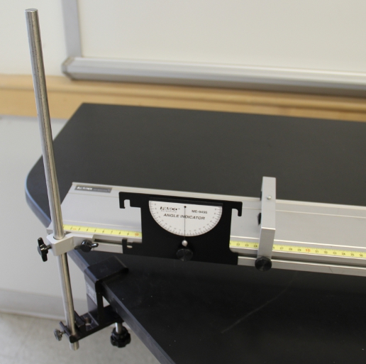
  2. Pasco Rotational Motion apparatus (See the instructions on how to assemble this.):
  3. Smart pulley on 15 cm rod (C9.2)
  4. 2-C-clamps (A2.4)
  5. Mass set (1-10, 2-20, 2-50,1-100,2-200,1-500 gram) (C9.1)
  6. 50 gram mass holder (C9.2)
  7. Vernier caliper (C9.4)
  8. 30cm metric ruler (C9.2)

General Class use :

  1. 2000 gram electronic balance (A2.3) at TA station (one per quadrant).

Notes and tests:

  1. Take calipers out of their boxes and return the boxes to the storage room somewhere that it will be easy to remember which ones are empty.
  2. Level all the platforms with a bubble level before it is clamped to the table.
  3. Start the test file “2305 Lab 9 test.cap”.   Spin the rotational platform. The rotation should register positve on the graph as the mass hanger falls toward the floor.
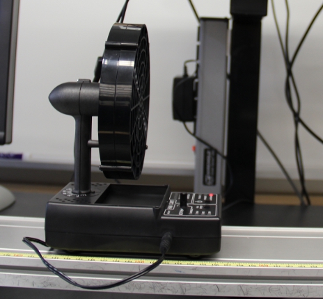
Objects subject to Left/Right Reflection

This is what your table should look like once set up

Additional Images below:

The General class setup.

There should be a scale like this at each TA Table

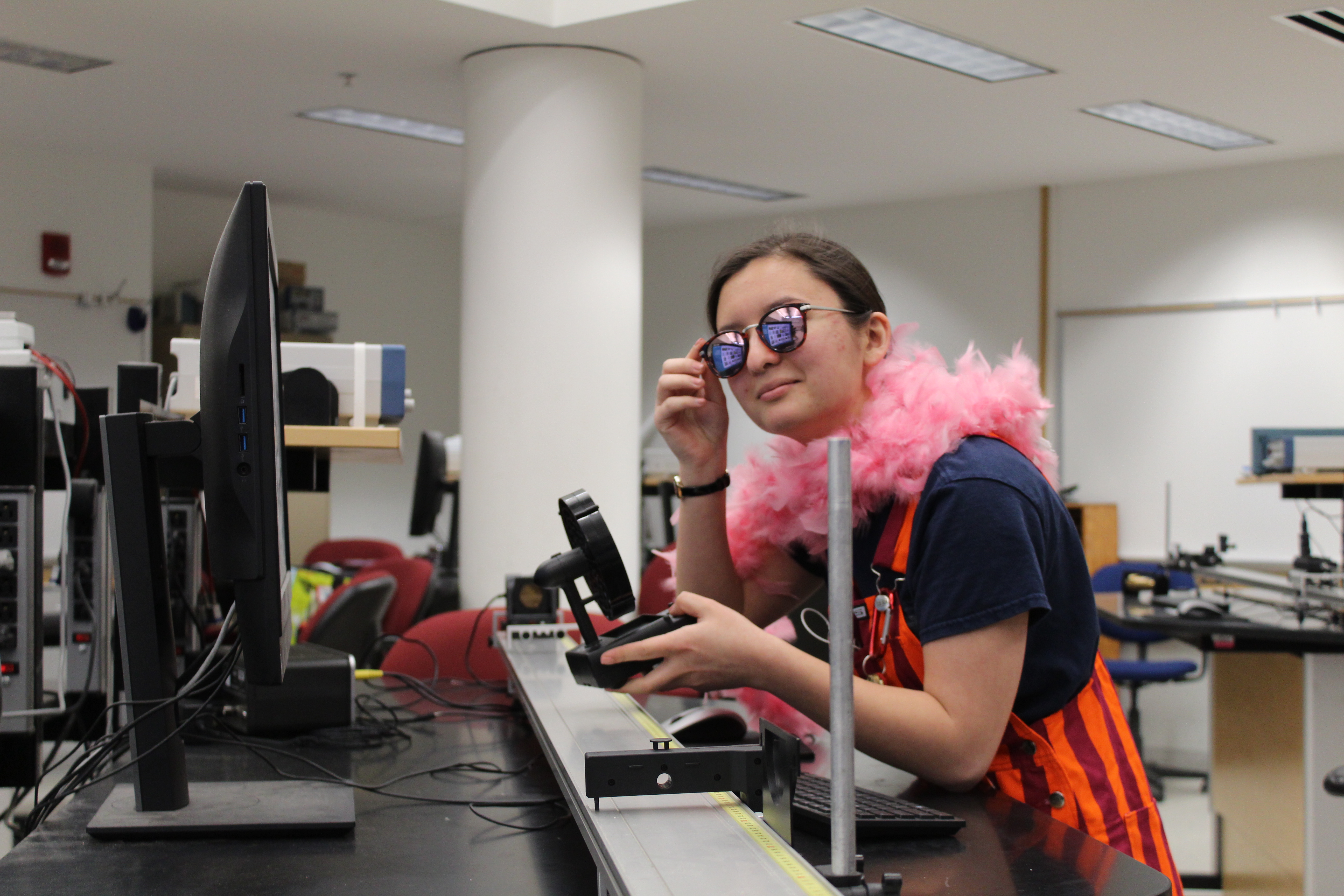
Clearly the most lovable lab

These should be evenly split between(C5.2, C6.2)

Caliper(C9.4) (Be sure to return the box to the closet).

Additional Instructions Below:

Instructions for attaching a string to the Shaft pulley of the Rotational system:

  1. Tie the string through the hole on the large shaft pulley.
  2. Loop the string around the pulley with the free end underneath the loop.
  3. Place the loop over the large pulley and pull it tight. This provides a strain relief for the hole in the plastic shaft pulley. If this is not done then when the falling weight reaches the bottom the string will pull through the hole in the plastic shaft pulley.

Instructions for assembling the RMS to the shaft of the Rotational system:

  1. The RMS adapter slides into a hole in the "A" base and into the rod clamp of the RMS. This should be gently tightned. The RMS needs to have the pulley on side without the PASCO label. The PASCO label should be facing up.
  2. The other pulley on the bottom leading from the rotational platform needs to be on upside down.
  3. The O-ring is placed around the two pulleys underneath the "A" base. The O-ring needs to be on the middle size pulley on both the shaft and RMS. Tension in the o-ring is provided by loosening the screws on the RMS adapter and pulling the RMS body away from the rotational shaft. The screws are then retightned. The O-ring doesn't need to be very tight, just snug so that the two shaft will rotate together.