This image does not really represent this lab and shouldn't be used to dictate set up.
Transition notes:
- The following can stay from the previous lab (2305 lab 4)
- 850 Interface
- USB - mini USB cord
- Cart Track
- 3 x Track End Stops
- 4 x Track Feetsies
- 2 x Track Feet Brackets
- 5 x Long Track Screws
- 1 x Short Track Screw
- Track Angle Indicator
- Plumb Bob
- Hanging Mass Set
- Mass Hanger
- 2 x Force Probe Hooks
- Elevation Clamp
- 45cm Rod
- Both Smart Carts (red and blue)
- 2 x Smart Cart Chargers
- 1.75m String
- PASCO Track Pulley
- Don't forget to SWEEEEEEEEEEEEEEP!
Equipment List:
- 850 Interface
- USB-mini USB cord
- Smart Cart - Red
- Smart Cart - Blue
- 2 x Smart Cart Charging Cord
- 2 x Bumper Accessory Bracket
- 2 x Brass Posts
- Bumper Spring Heavy
- 2 x Cart mass - 500g
- Magnetic Cart Bumper
- Friction Pad
- 2 x Force Probe Hook
- 45cm Rod
- Cart Track
- 3 x Track End Stop
- 4 x Track Feet
- 2 x Track Feet Bracket
- 5 x Long Track Screw
- 1 x Short Track Screw
- Track Angle Indicator
- Plumb Bob
- Elevation Clamp
- Right Angle Clamp
- Large Universal Clamp
- Track Pulley (Pasco)
- 2 x 8 N/m Spring
- String - 1.75 m
- 1 Meter Stick
- 50g Mass Hanger
- Hanging Mass Set with the following masses:
- 1 x 10g mass
- 2 x 20g mass
- 2 x 50g mass
- 1 x 100g mass
- 2 x 200g mass
- 1 x 500g mass
- Electronic Balance
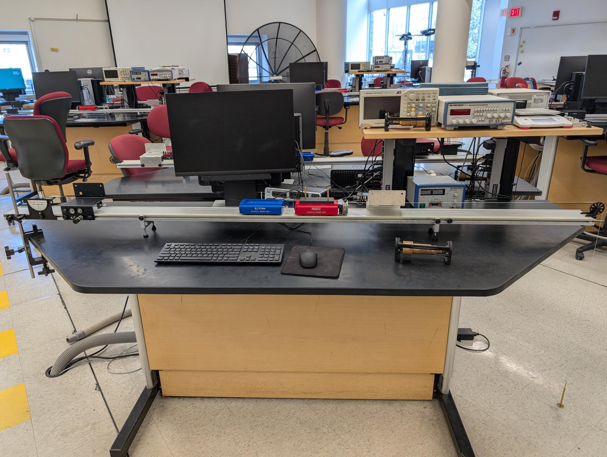
This is what your table should look like once set up
Additional Images below:
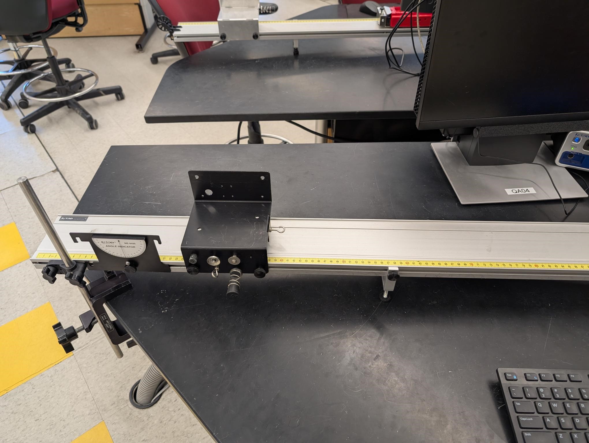
Left Side of Setup
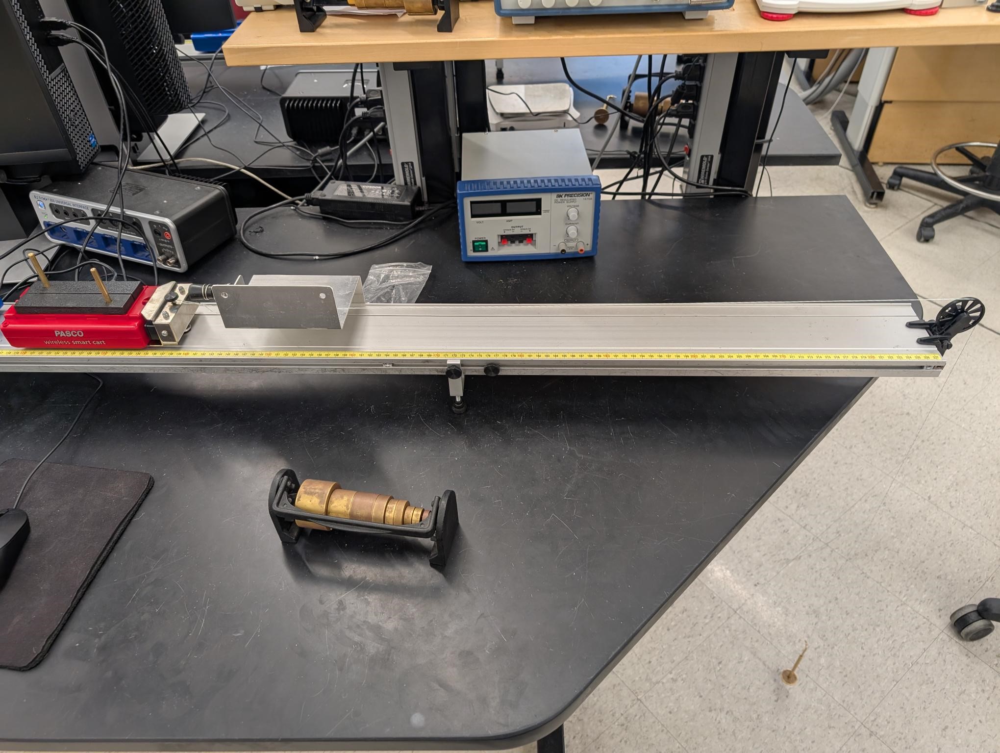
Right Side of Setup


![[HOME]](../../images/Mis/home2.GIF)
![[PREV]](../../images/Mis/arrow2.GIF)
![[PREV]](../../images/Mis/arrownew.gif)