Revised 07/18/2016

Physics 2305 Laboratory Equipment List

Lab 6: Conservation of Energy

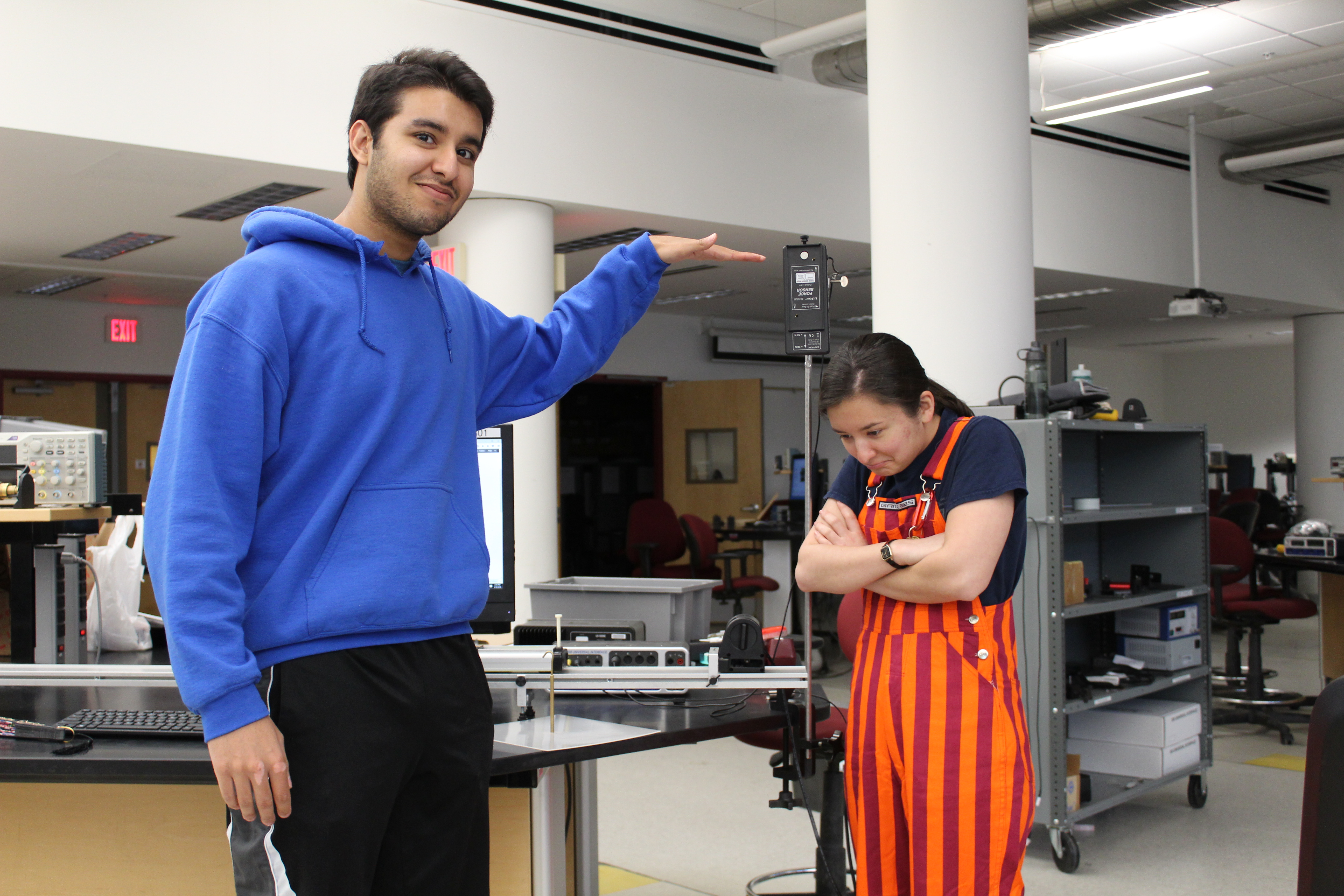
Lovedeep Holding his hand near a mounted forceprobe as if to say you must be this tall to ride. Erika pouting undering because she is too short.

You must be "this tall" to ride.

Transition notes:

  1. Leave out the track with elevation rod, mass sets, and one of the thumb screws from attaching the bumper accessory.
  2. Detach the force sensor from the bumper accessory bracket. Leave out the force sensor, and put the bumper accessory bracket as out of the way as possible.
  3. Detach the acceleration sensor from the dynamics cart. Remove the friction bracket, but leave it out. Put away Dynamics cart with the force sensor attached and the acceleration sensor/bracket and 8 pin DIN cable.
  4. Put away the RMS, pulley on rod, spring scale, string, and springs (different springs go out this lab).
  5. The only additions will be another 45cm rod, different springs, collision cart with friction pad, and a sail.

Equipment List:

  1. 850 Interface with the following sensors:
    • Motion Detector with
      yellow plug DG1, black plug DG2
    • Force Probe (Analog A)
  2. Cart Track
    • Elevation Clamp
    • on the left side clamped to the 45cm Rod sitting in a [Medium Clamp not yet in JSON File]
    • Angle Indicator attached with a Short Track Thumb Screw
  3. Collision Cart
  4. Friction Pad
  5. Hanging Mass Set with the following masses:
    • 1 x 10g Mass
    • 2 x 20g Mass
    • 2 x 50g Mass
    • 1 x 100g Mass
    • 2 x 200g Mass
    • 1 x 500g Mass
  6. Vertical Support for Force Probe and Spring:
    • 90cm Rod
    • 45cm Rod
    • Right Angle Clamp
    • Large Universal Clamp
  7. Scale
  8. Spring
  9. Plastic Sail

Notes and tests:

  1. Using the the test file, in tab 1 move the cart in front of the Motion Sensor and in tab 2 push/pull the force probe. They should register on the graph.
  2. It is important that there be a screw in the force probe to secure it to its support. Make sure when mounting the force probe on the rod it is slid all the way to the front so that none of the rod is poking out.
  3. Make sure both screws to the elevation rod are firmly clamped, so the rod cannot slip.
  4. Make sure all carts have friction pads.
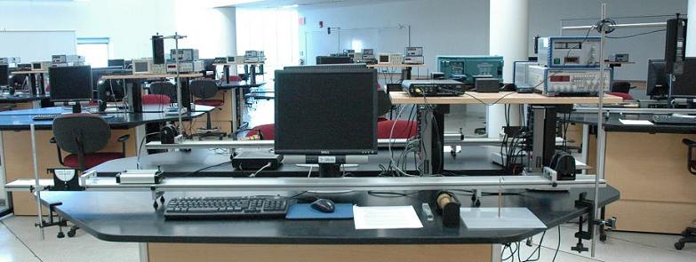
Full table set up of the Conservation of Energy lab. The force probe assembly is on the right and the elevation clamp is on the right. The mass set, spring and scale are neatly set out on the table and the collision cart is on the track.

This is what your table should look like once set up

Additional Images below:

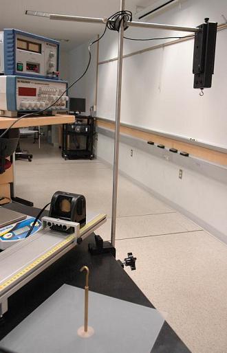
The force probe mounted ont eh 45 cm rod all the way at the end. The wire is wrapped around the right angle clamp and then plugged into the interface to prevent it from getting in the way. This assembly is on the same side as the motion detector.

Try to position the Force Probe so that it blocks as little walkway as possible.

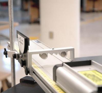
The left side of the track with a collision cart near an end stop with the angle indicator on the other side of the end stop. It's a pretty picture with interesting depth of field but not very useful.

This is a useful picture!