![[Virginia Tech Department of Physics]](../../images/Mis/vtphyslogo2.gif)
Transition notes:
- The following can stay from the previous lab (2306 Lab 9):
- 850 Interface
- A-Base
- Both black Banana Cords (remember you will need to add another one for this lab to make a total of three)
- Both red Banana Cords (remember you will need to add another one for this lab to make a total of three)
- Both black Banana to Alligator Adapters (you will need to add two more for a total of 4 for this lab)
- Both red Banana to Alligator Adapters (you will need to add two more for a total of 4 for this lab)
- Bar Magnet Box with all of it's contents
- Variable Gap Magnet
- 45cm Rod
- USB-A to USB-Mini Cord
Equipment List:
- 850 Interface
- A - Base
- 3 x Black Banana Cord
- 3 x Red Banana Cord
- 4 x Black Banana Plug to Alligator Adapter
- 4 x Red Banana Plug to Alligator Adapter
- Voltage Sensor
- Rotary Motion Sensor (does not need to be plugged in!!!!)
- Screw, Thumb - Extended RMS
- 2 x Rod - 45cm
- Right Angle Clamp
- Bar Magnet Box
- 2 x Bar Magnet Keeper
- 2 x Bar Magnet (Cyclindrical)
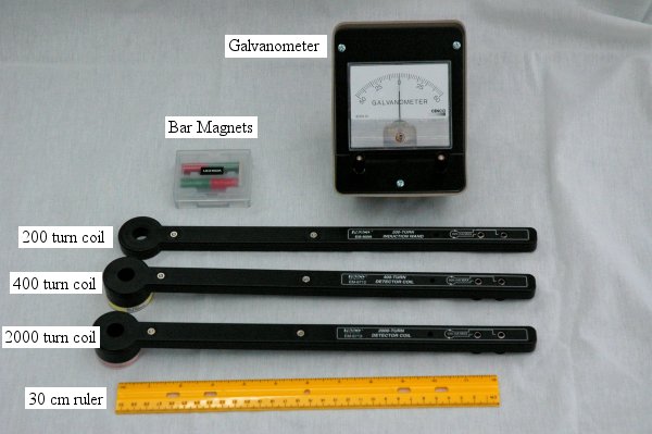
- Induction Wand - 200 Turn
- Induction Wand - 400 Turn
- Induction Wand - 2000 Turn
- See the setup notes for more details.
- Helmholtz Field Coil
- Helmholtz Base
- Screw, Thumb - HelmholtzBase
- Oscilloscope
- 2 x BNC to Banana Plug Cable
- Shunt with no resistor (not yet in database, stored with wands)
- Shunt with a resistor (not yet in database, stored with wands)
- Function Generator
- BNC Tee
- BNC to BNC Cable
- BNC to Banana Plug Cable
- See the setup notes for instructions and images of the Helmholtz Coil set up.
- Magnet - Variable Gap
- Galvanometer
- Ruler Metric - 30cm
General Class use :
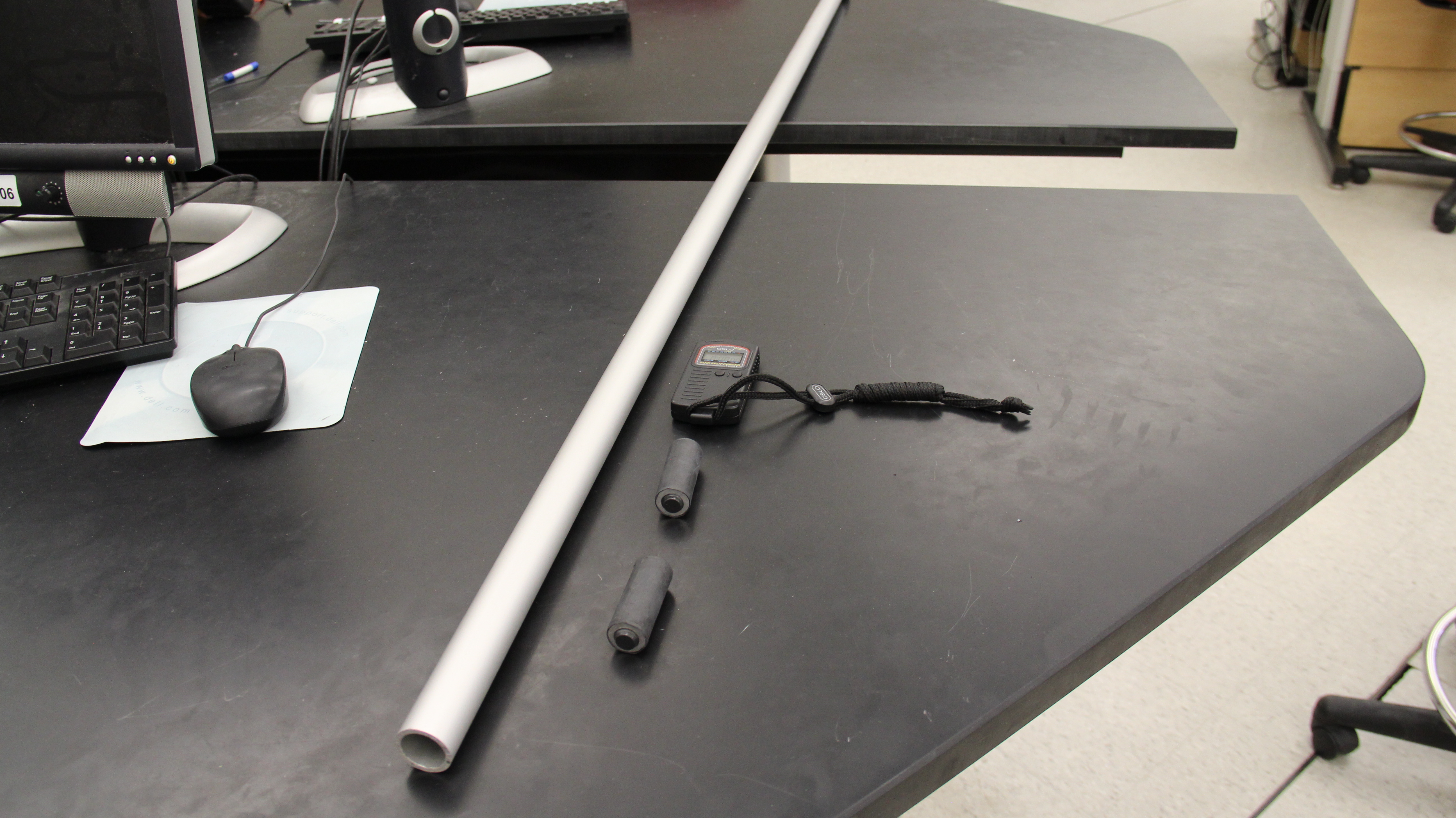
- Lenz's law demonstrator (1-2 per quadrant) placed on the TA table and a set up cart. The Lenz's law demonstrator consists of:
- Lenz's Law Demonstrator Tube
- Lenz's Law Dummy Magnet
- Lenz's Law Magnet
- Stopwatch
Notes and tests:
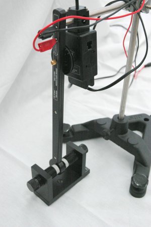
- Set up the A-base/RMS apparatus as seen in the setup notes. Attach the 200 turn induction wand to test the height so that it will swing through the center of the variable gap magnet.
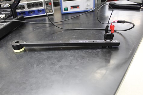
- Load the test file “2306 Lab 9 test.cap”. Drop a magnet through a coil wand attached to the voltage probe, and check that the induced voltage is registered.
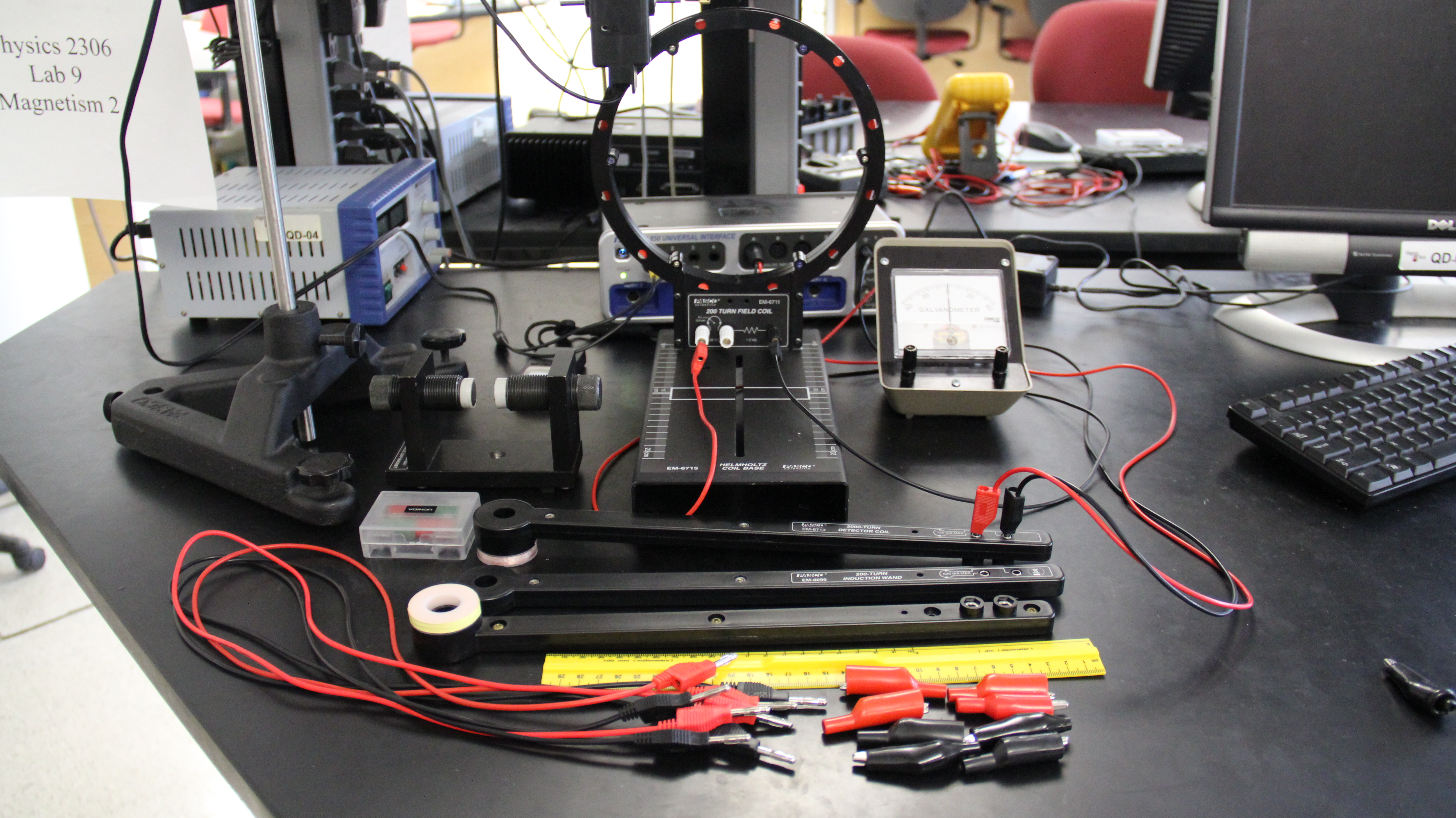
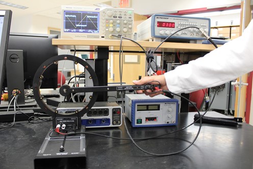
- Hook the voltage probe to an induction wand and the power amp to the large coil as in the picture. Test that the interface is putting out a current and when you put the wand in the middle of the coil and move it around you get changes in the induced voltage.


![[HOME]](../../images/Mis/home2.GIF)
![[PREV]](../../images/Mis/arrow2.GIF)
![[PREV]](../../images/Mis/arrownew.gif)