Transition notes:
- The following can be left out from the previous lab (2215 Lab 6: Forces & Acceleration)
- Electronic Balance - 2,200g, 0.1g Readability
- LabPro Interface
- LabPro Interface Power Supply
- USB-A to USB-B Cord
- Don't forget to SWEEEEEP!!!
Equipment List:
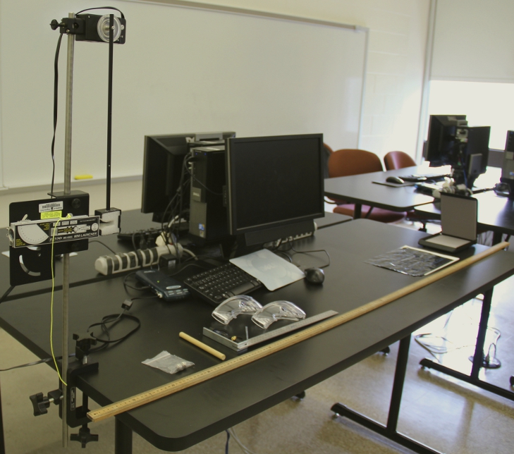
- Computer - 2000 level Desktop
- LabPro Interface
- LabPro Interface Power Supply
- USB-A to USB-mini USB cord
- Vernier Rotary Motion Sensor in DIG1
- Rotary Motion Sensor Wheel connected with the largest pulley the furthest from the sensor.
- Ballistic Pendulum Attachmentwith a long screw in it attached to the wheel.
- 90 cm rod
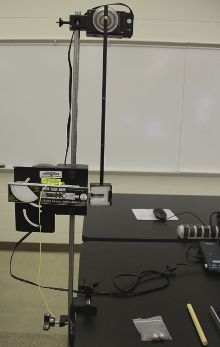
- Mini-Launcher
- Large Universal Clamp
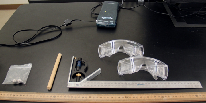
- Cocking Rod
- 1 Pair (bagged) Ball Steel-16mm
- 3 Pairs of Safety Goggles
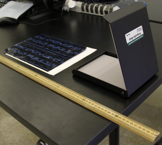
- Projectile Stop
- Carpenters Square Base
- Carpenters Square Ruler (the base and ruler should be together)
- 2 meter stick
- Carbon Paper
- A few sheets of Plain Paper
General class use:
- Electronic Balance
- Disinfecting Wipes. Also place another 1 or 2 containers around the room in a visible spot.
- Masking Tape
Notes and tests:
- The ballistic pendulum launcher should be set up to launch the projectile away from the nearest other setup.
- Make sure the gun is pushed back to be level with the metal framing and it is pointing straight.
- Make sure when fired the ball gets caught in the styrofoam. There are various slight adjustments that can be made to fix this. Ask your supervisor.
- Disinfect all Safety Goggles.
- Open the file "ballistic.cmbl" to test. When the ball is caught, the angle should go above 50 degrees.


![[HOME]](../../images/Mis/home2.GIF)
![[PREV]](../../images/Mis/arrow2.GIF)
![[PREV]](../../images/Mis/arrownew.gif)