![[Virginia Tech Department of Physics]](../../images/Mis/vtphyslogo2.gif)
Transition notes:
- The Pasco interface and sensors are not used. All the sensors should be put away.
- Switch the component bags.
- Put out the BNC cables.
- Place the power supply from the lab table back on the shelf.
- Remove batteries from board to be tested later.
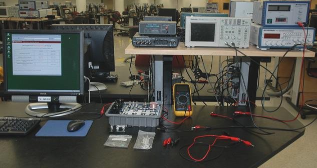
Equipment List:
- Circuit Board with the following on it:
- 3 x 2.47V light bulb (#C14)
- Telegraph Switch (AKA telegraph Switch)
- 5 x 10cm Jumper Wire
- 5 x 25cm Jumper Wire
- Lab 7/10 Component bin:
- 2 x 10 Ohm Resistor
- 2 x 560 Ohm Resistor
- 2 x 100 kOhm Resistor
- 2 x 1 μF Capacitor
- 3 x 10 μF Capacitor
- 2 x 100 μF Capacitor
- Oscilloscope
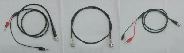
- Function Generator With the following cables attached:
- BNC Tee
- BNC to BNC Cable connected from the Tee to CH1 of the scope
- BNC to Banana Plug Cable connected to the Tee
- BNC to Alligator Clip Cable connected to CH2 of the scope
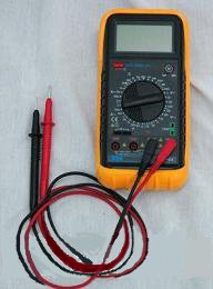
- Digital Multimeter with:
- Red multimeter lead
- Black multimeter lead
- Loose Cables and adapters:
- 3 x Red Alligator Cord
- 3 x Black Alligator Cord
- 4 x Red Alligator Clip (all but 1 attached to banana plugs)
- 4 x Black Alligator Clip (all but 1 attached to banana plugs)
- SPDT Knife Switch
Notes and tests:
- Turn on the oscilloscope and check that the "OpenChoice" software can read data from the oscilloscopes.
- The BNC to alligator clip cable is plugged into channel 2 of the oscilloscope, and the BNC to banana plug cable is plugged into the "T" attached to the output of the function generator.
- Check that the function generator produces clear signals with all waveforms at all but the highest ranges
- Reset the Oscilloscope to "Default Setup".
- Check that each station has the proper equipment from the previous lab. Straighten all the equipment.
- Check everything is in the components bins including one extra of each item. Put extras on TA cart.
- Make sure the voltage is set all the way down and the current is at the 9 O'clock position on all power supplies.


![[HOME]](../../images/Mis/home2.GIF)
![[PREV]](../../images/Mis/arrow2.GIF)
![[PREV]](../../images/Mis/arrownew.gif)