![[Virginia Tech Department of Physics]](http://www.phys.vt.edu/~demo/images/Mis/vtphyslogo2.gif)
Transition notes:
- Everything from the previous lab can stay, EXCEPT FOR:
- All 3 of the 2.25V light bulbs
- All 5 of the 33 Ohm resistors
- Remove the used batteries to the testing box, and put out 2 fresh ones for each board.
- Sweep! Please!
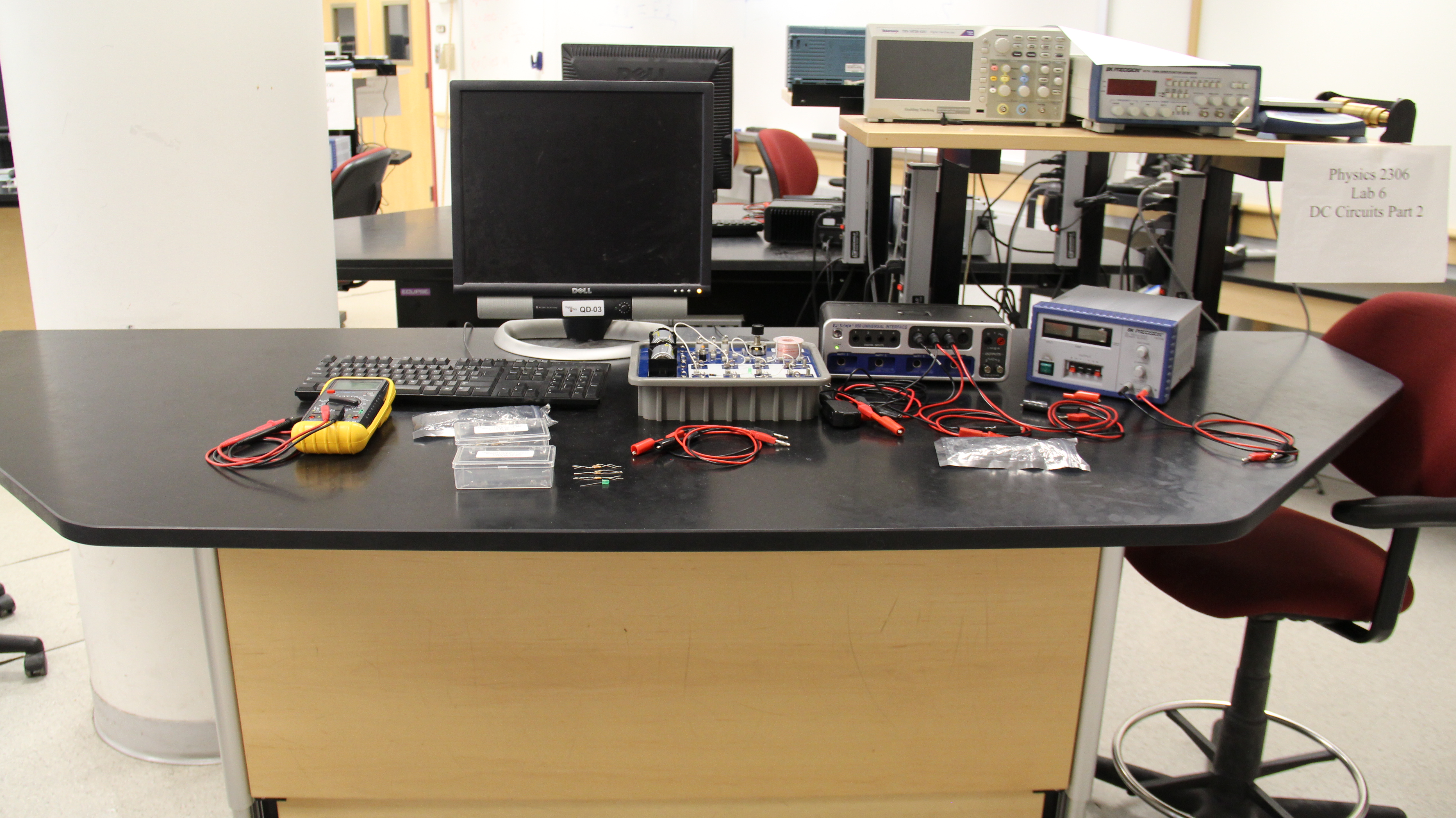
Equipment List:
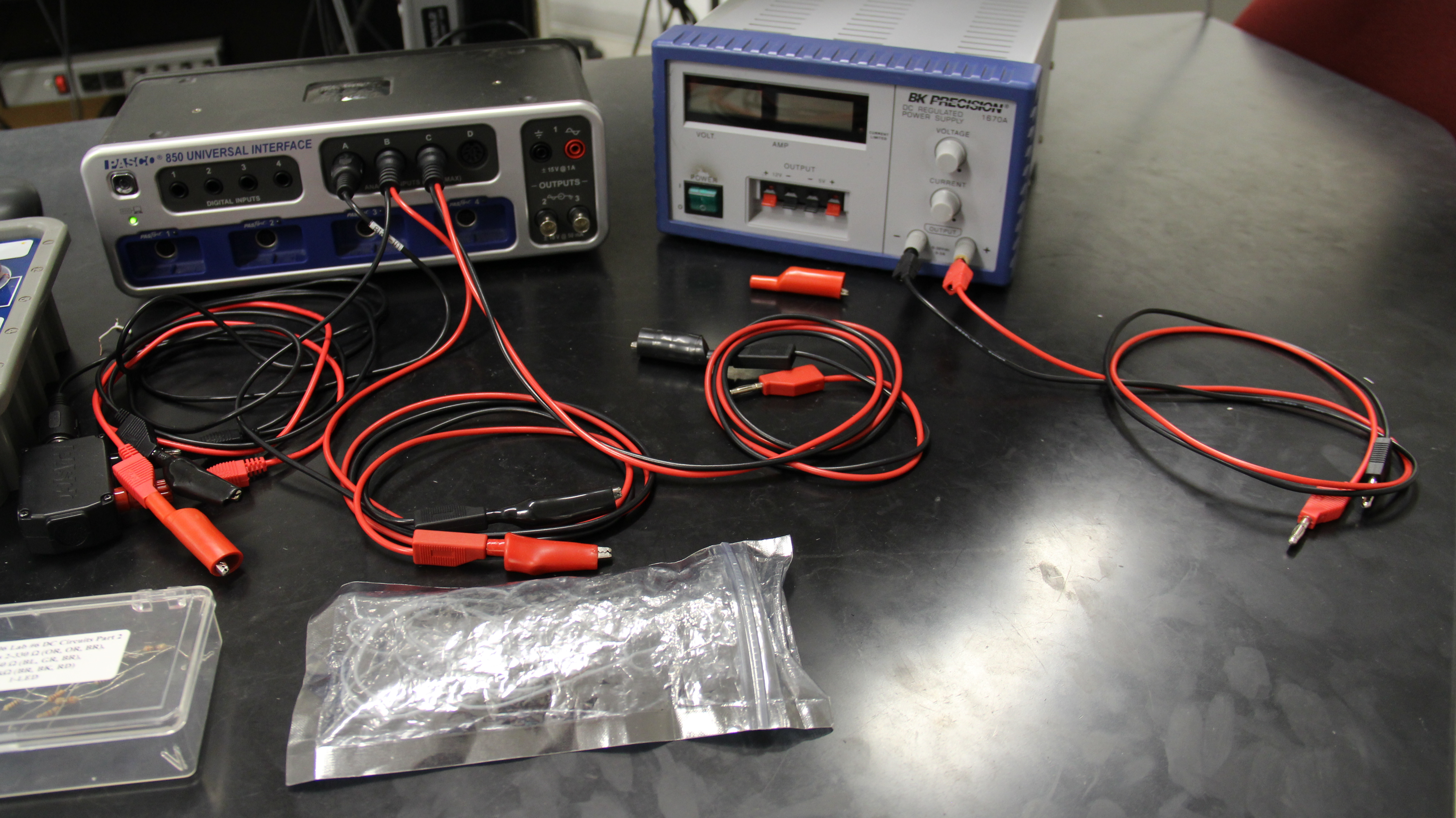
- 850 Interface
- USB-A to USB-mini USB cord
- Current Sensor
- 8 pin DIN extension cable
- 2 x Voltage Sensor
- Current limited Power Supply
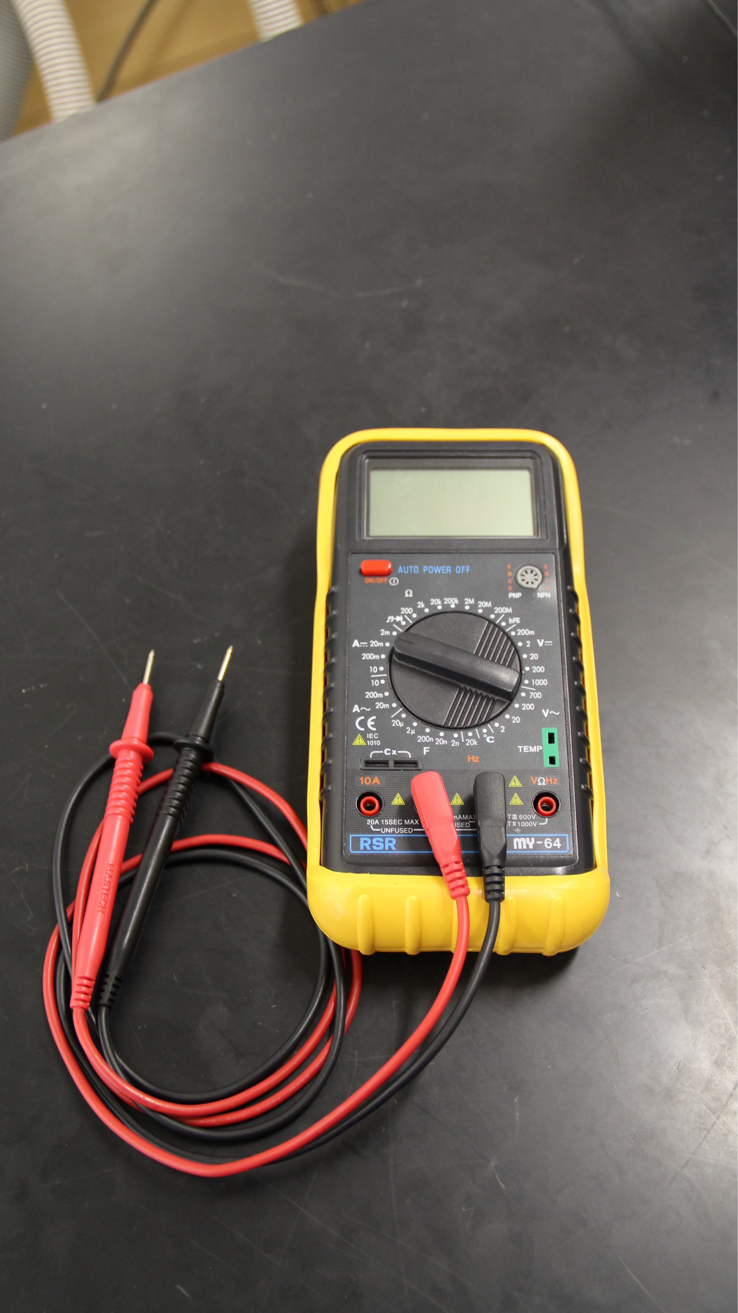
- Multimeter
- Red DMM Probe (multimeter lead)
- Black DMM Probe (multimeter lead)
- Circuit Board
- 2 x D cell battery
- Spring Switch (AKA telegraph Switch)
- 5 x 10cm Jumper Wire
- 5 x 25cm Jumper Wire
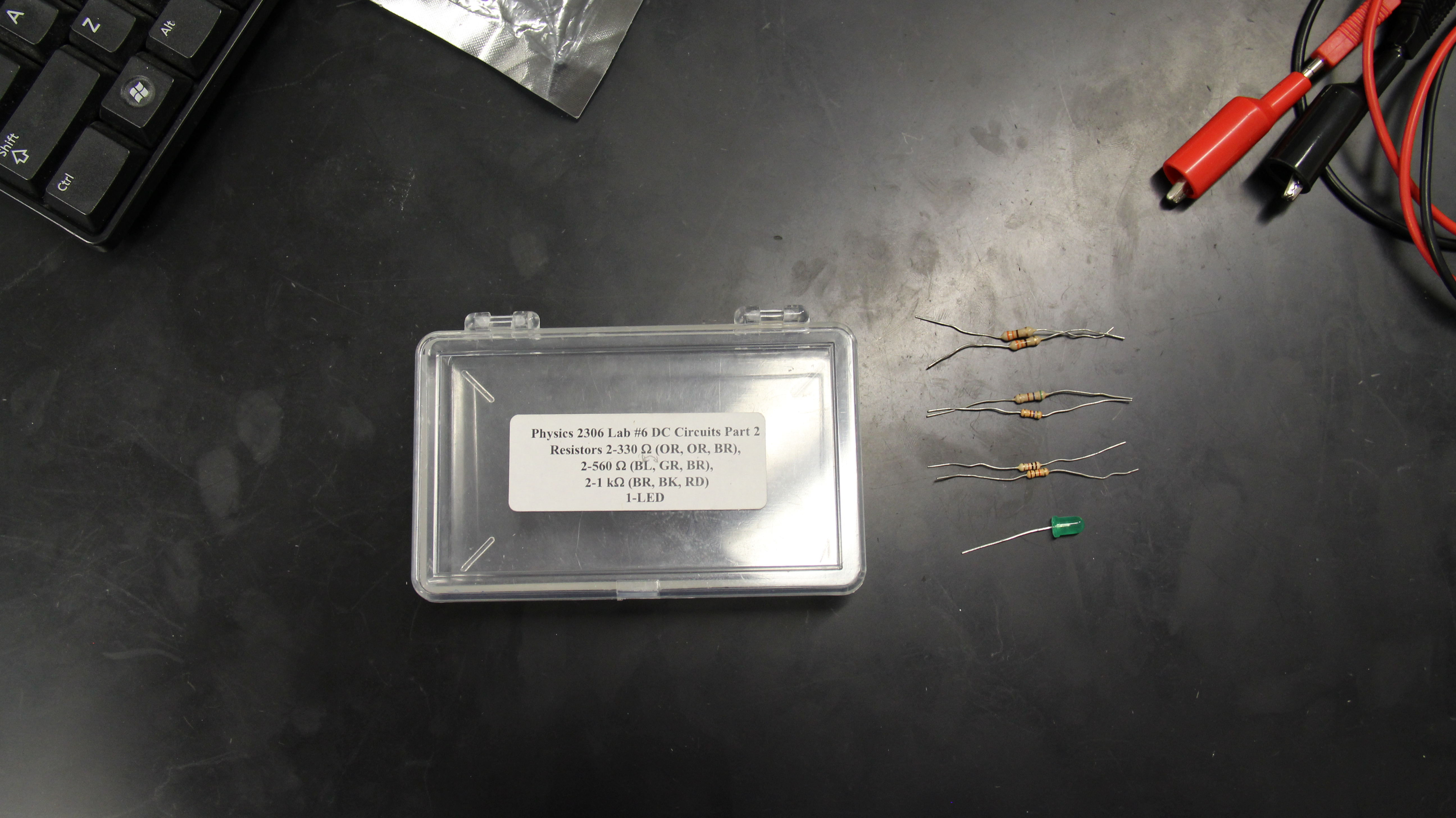
- Lab 7 Component bag:
- 3 x 330 Ohm Resistor
- 3 x 560 Ohm Resistor
- 3 x 1 kOhm Resistor
- 3 x Green LED
- 3 x Red Alligator Cord
- 3 x Black Alligator Cord
- 4 x Red Alligator Clip (all but 1 attached to banana plugs)
- 4 x Black Alligator Clip (all but 1 attached to banana plugs)
Notes and tests:
- Put alligator clip adapters on: both voltage probes, banana plugs coming out of the current sensor with alligator clip adapters on the end.
- Test all batteries to pass at least at the 80% level on the battery tester.
- Plug the remaining set of banana plug cables into the DC power supply and set it on the lab table.
- The current limit knob should be set to 9 o’clock position.
- Place the power supplies on the table. Test the power supplies with multimeter, and then turn the voltage to zero.
- Test the voltage sensors and current sensor with the test file "2306 Lab 6 test.cap" by setting up a simple circuit with the batteries and a bulb.
- Make sure that there is a supply of components in the TA cabinet.


![[HOME]](../../images/Mis/home2.GIF)
![[PREV]](../../images/Mis/arrow2.GIF)
![[PREV]](../../images/Mis/arrownew.gif)